English
  中文简体
中文简体 
Content
- 1 What Is a Pressure Reducing Valve and How Does It Work?
- 2 Tools You Need Before You Start
- 3 Step-by-Step: How to Adjust a Pressure Reducing Valve
- 4 How to Adjust Without a Pressure Gauge
- 5 How to Tell If Your PRV Needs Adjustment (Common Signs)
- 6 Troubleshooting: What If the Pressure Does Not Change?
- 7 Pressure Reducing Valve Materials: Does the Housing Matter?
- 8 PRV Adjustment Safety Tips
- 9 What Correct Adjustment Behavior Tells You About How a PRV Is Built
- 10 Performance Reference Across Our PRV Housing Product Lines
- 11 Where These Valves Are Installed in the Field
- 12 Quality Control From Casting to Final Test
- 13 Custom Manufacturing, Packaging, and Global Shipping
- 14 Frequently Asked Questions
- 15 Explore Our Pressure Reducing Valve Component Range
What Is a Pressure Reducing Valve and How Does It Work?
A pressure reducing valve (PRV) does one job: it takes a variable, often high inlet pressure and delivers a steady, lower outlet pressure no matter what is happening upstream. When that outlet pressure drifts away from the set value, you rarely need a new valve. In most cases, you simply reset it. The adjustment screw on top changes the spring preload, and that single mechanical change controls the pressure the valve holds.
Understanding what happens inside makes the adjustment safer and more precise. Upstream pressure is the pressure entering the valve. Downstream pressure is the pressure leaving it, which is what your plumbing, tools, or production equipment actually experience. Inside the valve body, the adjustment screw presses on a spring. The spring pushes a diaphragm-and-stem assembly, and the stem regulates how far the valve seat opens. When downstream pressure matches the spring preload, the valve holds its position. When downstream pressure falls, the spring pushes the stem open to allow more flow. When downstream pressure rises, the fluid pushes back and the valve closes slightly.
This is why the direction of rotation matters. Turning the adjustment screw clockwise compresses the spring further and raises the outlet pressure. Turning it counterclockwise relaxes the spring and lowers the outlet pressure. The entire procedure is built on that simple rule.
Tools You Need Before You Start
Gather the right tools before you touch the valve. Using a pipe wrench on the housing or skipping a pressure gauge can turn a five-minute adjustment into a leaky repair.
| Tool | Purpose |
|---|---|
| Adjustable wrench or crescent wrench | Loosening and tightening the lock nut without scraping the housing surface. |
| Flathead or Phillips screwdriver | Turning the adjustment screw on valves that use a screwdriver slot instead of a hex head. |
| Pressure gauge | Measuring downstream pressure before, during, and after adjustment. Required for accurate results. |
| Bucket and dry rag | Catching small leaks from the test port and cleaning the work area. |
| Work gloves | Protection from hot surfaces, sharp edges, and system fluid. |
| Industrial extras: media-specific gauge, thread seal tape | Checking set pressure in air, hydraulic, or steam systems and resealing connection threads. |
For industrial systems, use a gauge that matches the medium. A water pressure gauge will not give reliable readings on a compressed air line, and the same applies to hydraulic oil and steam.
Step-by-Step: How to Adjust a Pressure Reducing Valve
The standard procedure has five steps. Each step includes what to do and why it matters.
Step 1: Locate the PRV
In a residential system, the PRV is normally installed just after the main shutoff valve, close to the water meter or where the service line enters the house. Look for a bell-shaped or dome-shaped metal body with an adjustment screw and lock nut on top. A flow-direction arrow is usually cast into the housing. In industrial systems, the PRV is typically part of an FRL unit on a compressed air line, at the outlet of a hydraulic power unit, or at the inlet of a steam distribution line.
Step 2: Measure the Current Pressure
Attach a pressure gauge to the nearest hose bib, test port, or drain valve. Make sure no water or air is being used at the moment. Record the static pressure before you change anything. If the reading is already inside the acceptable range, the valve may not need adjustment at all. For industrial lines, confirm that the gauge range covers at least 1.5 times the expected set pressure to avoid over-pressurizing the gauge.
Step 3: Loosen the Lock Nut and Turn the Adjustment Screw
Use the adjustable wrench to loosen the lock nut. You do not need to remove it, only break it free so the adjustment screw can rotate. Then turn the screw in small increments. Clockwise increases the outlet pressure; counterclockwise decreases it. A quarter turn, roughly 90 degrees, is a safe starting interval for most valves between 20 and 120 psi.
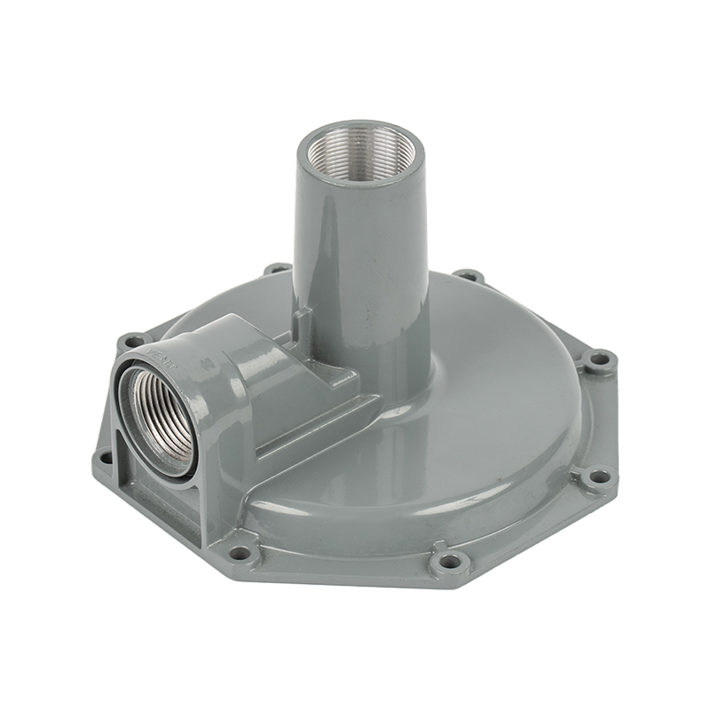
Do not crank the screw in one large sweep. A sudden change in spring preload forces the diaphragm to rebalance quickly, which can cause pressure overshoot, water hammer, or seat damage. Slow and small is always better. The feel of the screw also tells you something about the valve. Clean, smooth rotation indicates a well-machined housing; a gritty or binding thread often points to a low-quality body. A precision-machined PRV body with a fine thread finish gives predictable, repeatable feedback with every quarter turn.
Step 4: Recheck the Pressure and Fine-Tune
After each adjustment, wait 15 to 30 seconds for the system to stabilize, then reread the gauge. Repeat the quarter-turn method until the downstream pressure reaches your target. For residential water systems, 40 to 60 psi is the common working range, and the setpoint should not exceed 70 to 75 psi. For industrial systems, follow the design pressure of the downstream equipment, not a generic number.
Step 5: Tighten the Lock Nut and Verify Again
Hold the adjustment screw in place with one wrench and tighten the lock nut with a second wrench. This prevents the screw from rotating as you lock it. Once the lock nut is snug, take one final pressure reading, ideally with a flow running, to confirm the setpoint holds. Check around the valve body, the test port, and the connections for any leakage.
How to Adjust Without a Pressure Gauge
If no gauge is available, you can still make a rough adjustment, but treat it as temporary. Turn the screw a quarter turn clockwise and run a tap or open a downstream valve. If the flow becomes noticeably harder or spray patterns get more aggressive, the pressure went up. Turn counterclockwise and the flow softens. On compressed air systems, watch the actuation speed of a cylinder or the fill time of a receiver. Faster actuation means higher pressure.
This method only tells you the direction of change, not the actual value. Install a gauge as soon as possible and calibrate the setpoint properly.
How to Tell If Your PRV Needs Adjustment (Common Signs)
Several signs point to a pressure problem before you ever touch a wrench.
- Water hammer or banging pipes after a tap closes, which usually means the downstream pressure is set too high and the check valves or faucets are slamming shut.
- Water that splashes aggressively from faucets, or a shower that feels overly forceful.
- A water heater temperature-and-pressure relief valve that discharges water periodically, a warning that supply pressure is exceeding the safe range.
- Recurring leaks at washing machine hoses, faucet seals, or appliance inlet connections.
- Weak spray from a shower, long fill times for tanks, or appliances that underperform, which points to pressure set too low.
- Slow cylinder actuation or low force from actuators in compressed air and hydraulic systems.
If a valve worked correctly for years and then drifted, suspect spring fatigue, a fouled seat, or a shift in the inlet supply pressure. Adjustment is the first remedy, but it is not always the final fix.
Troubleshooting: What If the Pressure Does Not Change?
You loosened the lock nut, turned the screw, and the gauge did not move. Before assuming the valve is broken, check these causes in order.
- Lock nut not fully loosened. The nut can still clamp the screw threads and prevent rotation. Loosen it until it spins freely.
- Adjustment screw at the end of its travel. The screw has a finite range. If it is already fully in or fully out, turning it more does nothing. Back it off and reassess the system design.
- Diaphragm damage or spring fatigue. A torn diaphragm will not transfer spring force to the valve stem, and a work-hardened spring will not hold preload. Both require valve replacement, not adjustment.
- Clogged internals or debris on the seat. Dirt prevents the seat from sealing and the diaphragm from sensing pressure correctly. Flush the line and, if necessary, clean or replace the valve.
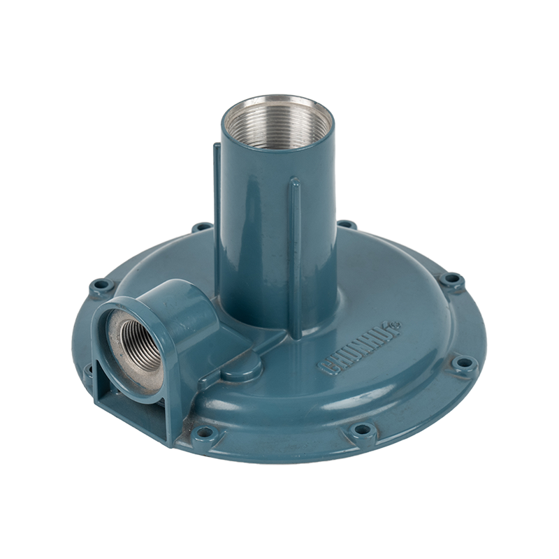
Repeated internal failures are often a sign of marginal housing quality. If the bore surface corrodes or the body deforms under load, the stem binds and the setpoint drifts no matter how carefully you adjust it. For high-cycling industrial systems, a high-strength aluminum alloy PRV body resists deformation and keeps the spring and stem aligned over years of service.
Pressure Reducing Valve Materials: Does the Housing Matter?
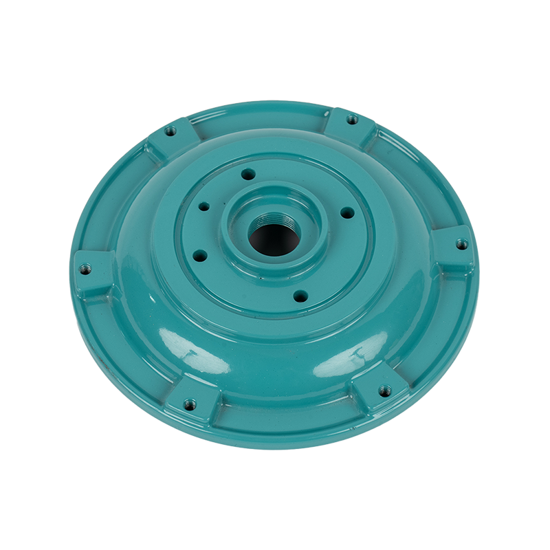
The housing is not just a shell. It holds the spring, diaphragm, and seat in precise alignment, and it is the surface you grip, thread, and read pressure through. Housing quality directly affects how well the valve responds to adjustment. For a complete view of available options, see our pressure reducing valve housings overview.
Brass has been the traditional material for residential PRVs, and it remains a sound choice in many conditions. Aluminum die-cast housings, produced by precision die casting, offer a different balance of properties that suits modern, lightweight, and thermally demanding systems.
| Criterion | Brass housing | Aluminum die-cast housing |
|---|---|---|
| Weight | Heavier | Lighter, easier to handle and install in confined spaces |
| Corrosion resistance | Good in freshwater; must be matched carefully to aggressive media | Excellent when finished with a corrosion-resistant coating for humid or chemically exposed locations |
| Thermal conductivity | Moderate | Higher, which helps dissipate heat in warm operating environments |
| Machining precision | Good, but thread quality can vary with casting method | Consistent dimensions, smooth thread surfaces, and fine finishes from precision die casting |
| Typical applications | High-pressure steam, chemical service, traditional plumbing | Residential water, compressed air, hydraulic circuits, integrated and lightweight designs |
For humid or chemically exposed environments, a corrosion-resistant pressure reducing valve housing prolongs service life and keeps the adjustment mechanism reliable for decades. In any housing, look for an even surface without porosity, clean threads, and uniform wall thickness. These indicators are controlled by the casting process itself. Manufacturers operating certified quality systems, such as ISO 9001:2015 and IATF 16949:2016, are more likely to deliver that consistency.
PRV Adjustment Safety Tips
Adjustment is a low-risk task, but only when the system is prepared correctly.
- Confirm the line is at normal operating pressure before measuring, but be ready to isolate or bleed it if you need to open a test port.
- On hot water systems, expect high temperatures. Wear gloves and direct any discharge away from your body.
- For compressed air and hydraulic systems, isolate the downstream side or bleed it to a safe level before opening fittings.
- Never exceed the rated pressure printed on the valve nameplate. The adjustment range stops at the design limit for a reason.
- Do not stand in front of a relief port or discharge opening while adjusting. A stuck valve can vent suddenly.
- Avoid pipe wrenches on the housing. Their teeth damage protective coatings and leave stress points that shorten service life.
If the valve will not adjust inside its normal range, or the pressure still drifts after a correct setup, the housing or internal components may be at the end of their service life. Replacing the valve is safer than forcing an overtightened screw.
What Correct Adjustment Behavior Tells You About How a PRV Is Built
A valve that responds cleanly to a quarter turn, holds its setpoint under flow, and does not creep back over the following days is not an accident. It is the result of dimensional control that starts long before the valve ever reaches a job site. Every mechanical link in the chain — the thread pitch on the adjustment screw, the flatness of the diaphragm seat, the concentricity of the bore that guides the stem — has to stay within a narrow tolerance band for the spring-and-diaphragm relationship described earlier in this guide to behave the way it should.
This is the part of the process that a technician in the field never sees directly, but feels through the wrench. A body cast with porosity or machined with an inconsistent bore will still pass a basic pressure test on day one, then drift, stick, or leak within months once thermal cycling and repeated adjustment expose the weak points. Our production floor treats the adjustment behavior described in the steps above as a design target, not just a field procedure — every housing is engineered so that a quarter turn produces the same, predictable pressure change whether it is the first adjustment after installation or the fiftieth adjustment several years later.
Brass alloy and aluminum ingot are checked against composition and hardness specifications before casting, since inconsistent raw material is the most common root cause of a housing that machines unevenly.
Aluminum housings are formed under controlled shot pressure and die temperature to minimize porosity, giving the bore and mounting faces a consistent starting surface before any machining begins.
The valve seat bore, diaphragm seat, and adjustment screw threads are finished on CNC equipment to tight tolerance, which is what gives the screw its smooth, gritty-free feel described in Step 3 above.
Spring, diaphragm, and stem are assembled under controlled torque, then every unit is pressure tested across its full adjustment range before it is packed for shipment.
Performance Reference Across Our PRV Housing Product Lines
Different jobs call for a different balance of weight, corrosion resistance, and pressure range. The table below lines up the housing families most often specified together with the guide above, so a plumbing contractor, panel builder, or OEM buyer can match a housing to the system it will actually see in service.
| Product Line | Typical Pressure Range | Best-Fit Media | Notable Advantage |
|---|---|---|---|
| Precision-Machined PRV Body | 20 – 120 psi | Potable water, general plumbing | Smooth, repeatable quarter-turn adjustment feel |
| High-Strength Aluminum Alloy PRV Body | Up to 250 psi, high-cycle duty | Compressed air, hydraulic circuits | Resists deformation under repeated pressure swings |
| Corrosion-Resistant PRV Housing | 20 – 150 psi | Humid, marine, or chemically exposed lines | Coating retains thread accuracy over years of exposure |
| Standard Brass Housing | 20 – 100 psi | Traditional residential and light commercial plumbing | Long field history, familiar to most technicians |
Notice that pressure range alone does not decide the right housing. A compressed air line running well within 120 psi can still wear out a residential-grade brass body faster than an aluminum alloy body rated for far higher pressure, simply because of cycle count. A valve that opens and closes dozens of times a minute in an automated pneumatic circuit experiences a completely different kind of fatigue than a household water line that adjusts once and then sits nearly static for months.
Where These Valves Are Installed in the Field
Municipal and Residential Water Supply
Here the priority is a stable setpoint that a homeowner or building maintenance team rarely needs to revisit. Municipal supply pressure can swing significantly between night and day demand, and a well-built PRV absorbs that swing without transmitting hammer or surges into fixtures. The five-step adjustment procedure covered earlier in this guide is written primarily with this application in mind, since it is the setting most technicians perform in the field.
Compressed Air and Pneumatic Automation
In an FRL unit ahead of a cylinder or pneumatic tool, the PRV cycles constantly and the housing experiences far more thermal and mechanical stress than a water line ever does. An aluminum alloy body with strong fatigue resistance keeps the regulator's response consistent, which matters directly for cycle time and repeatability on an automated line.
Hydraulic Power Units
Hydraulic circuits combine high pressure with oil that can be more aggressive toward seals and coatings than water or air. Housing bore finish becomes especially important here, since any surface irregularity accelerates seal wear and eventually leads to the internal leakage described in the troubleshooting section above.
Steam and Process Heating
Steam service adds a thermal cycling element on top of the mechanical stress every other application shares. Brass remains a common choice here precisely because of its long field history at elevated temperature, though the same dimensional-control principles described in this guide's manufacturing sections still decide whether a given brass body holds its setpoint reliably over years of thermal cycling.
Quality Control From Casting to Final Test
Because the field adjustment behavior described earlier in this guide depends entirely on internal geometry the installer cannot see, testing happens at multiple points long before a housing reaches a job site.
Bore diameter, thread pitch, and diaphragm seat flatness are measured against drawing tolerance on a sample basis from every casting run before parts move to final machining.
Cast surfaces are inspected for porosity and inclusions that could later show up as a slow leak path or an uneven adjustment feel once the valve is in service.
Assembled valves are cycled across their full adjustment range, from minimum to maximum setpoint, confirming that the response to a quarter turn stays consistent at every point in that range.
Each production batch is logged against its raw material lot and test results, so any field issue can be traced back to its casting run rather than treated as an isolated event.
Custom Manufacturing, Packaging, and Global Shipping
Standard housing dimensions cover most applications, but many customers need a bore size, thread pattern, or port configuration matched to an existing valve family or a specific downstream system. Our engineering team works from a customer's drawing or a sample part, confirms fit and pressure behavior on the bench, then scales the design into a repeatable production run.
Housings machined to a customer's own drawing, matching existing thread standards and port layouts for drop-in replacement parts.
Anodizing, powder coating, or plating selected to match the corrosion demands of the destination installation environment.
Individually protected components in carton or pallet packaging designed to prevent thread damage and surface marring during long-distance shipment.
Material certificates, dimensional inspection reports, and pressure test records prepared to match the destination country's import and quality requirements.
Frequently Asked Questions
Why does my valve feel gritty or uneven when I turn the adjustment screw?
An uneven feel usually points to thread quality on the adjustment screw or a bore that was not finished to a tight tolerance. As noted in Step 3 of the adjustment guide above, a precision-machined body should give smooth, consistent resistance through the entire quarter turn, not intermittent binding.
Is aluminum or brass better for a compressed air regulator body?
For high-cycle pneumatic duty, an aluminum alloy body generally holds dimensional accuracy better over millions of actuation cycles, while brass remains a strong choice for lower-cycle, higher-temperature service such as steam. The performance reference table earlier in this article lines up both options against typical pressure ranges.
How often should a PRV housing be inspected in an industrial setting?
There is no universal interval, but any of the warning signs described in the "Common Signs" section above — slow actuation, inconsistent pressure holding, or visible surface corrosion — should trigger an inspection regardless of a scheduled maintenance date.
Can a corrosion-resistant housing be specified for an existing valve design?
Yes. Housings can be produced to match an existing bore and thread pattern while upgrading only the surface finish or base alloy, which is a common request from customers replacing failed housings in humid or coastal installations.
What information do you need to quote a custom PRV housing?
A drawing or sample part, the intended operating pressure range, the media (water, air, hydraulic oil, or steam), and the installation environment are usually enough to begin an engineering review and provide a preliminary quotation.
Explore Our Pressure Reducing Valve Component Range
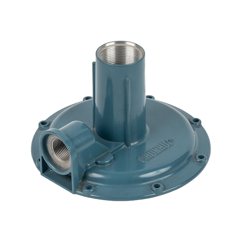
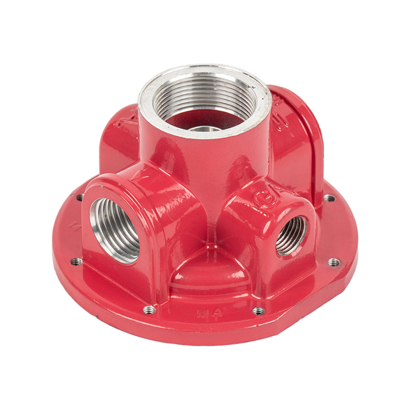
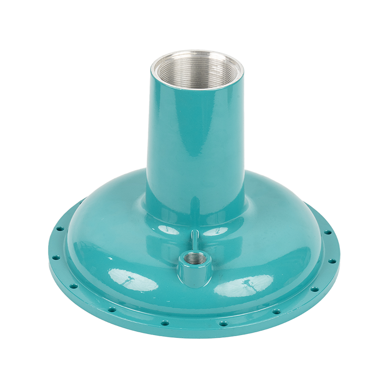
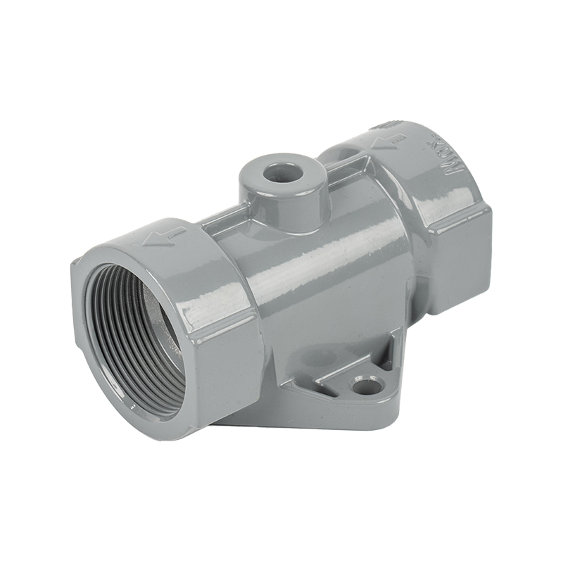
The manufacturing and material considerations covered above apply across our full range of PRV bodies and housings. A few of the product lines most often specified alongside the adjustment guidance in this article are shown below.