

 English
 When designing aluminum castings, you must take into account their application, appearance, performance, precision, and the significant cost. You need to determine the purpose of the part and balance your requirements to meet the budget. Here, we have highlighted the main matters that should be considered when designing the part.
Language
Home / Aluminum Die Casting Design Guide
Aluminum Die Casting Design Guide
The correct design method can significantly enhance your manufacturing experience. If you are involved in the die-casting industry or want to improve your knowledge of die-casting design, then this Aluminum Die-Casting Design Guide is exactly what you need. Mechanical engineers and product designers will find this design guide very useful. We have focused on introducing some important design factors and limitations, which can significantly simplify the aluminum die-casting process and thereby reduce production costs.
We offer a one-stop aluminum die-casting manufacturing service. Our engineers will carefully inspect every product we produce to ensure that each component is suitable for mass production. If you have any questions or concerns about the aluminum die-casting project, please feel free to contact us at any time.
Design Requirements
Using Function
When designing a product, its potential applications need to be considered. Aluminum die-cast parts can not only serve structural functions but also enhance aesthetics. Therefore, it has become a popular alternative to other materials.
Due to the fact that modern computers are much more powerful than before, the processing time has increased several times. The pressed parts not only have excellent structural importance but also possess excellent aesthetic functions.
You should clearly specify the purpose of the part on the die-casting machine. This can help you select the appropriate material and determine the appropriate tolerance for the design parameters based on your requirements. You should also consider the corrosion resistance, strength-to-weight ratio, conductivity, and other properties of the part.
However, customers often end up paying for quality and strength that far exceed their requirements. Therefore, fully understanding the functional use of the parts will help you better comprehend the die-casting process.
Appearance Requirements
For internal aluminum castings, appearance is not important. But for external castings such as shells or housings, appearance becomes very important.
End users always have a preference for aesthetically pleasing products. Therefore, regardless of the performance of the components, consumers will give priority to the appearance. Hence, the external die-cast parts should have an attractive appearance.
Therefore, when designing the parts, consideration should be given to the aesthetic aspect. Plan in advance the surface treatment effect you desire to achieve. Good surface treatment can provide additional protection against extreme weather conditions.
Assembly Method
The assembly process of aluminum castings can be relatively simple or very complex, depending on the complexity of the parts. Traditional casting equipment has certain limitations on the types of parts that can be cast. Therefore, it was previously very difficult to cast complex details.
However, complex parts can be divided into appropriate sections and then connected together through suitable assembly methods after casting. Some common die-casting assembly techniques include:
- Fastening
- Thread
- Welding
- Injection-molded metal components
- Core drilling holes, etc.
Before starting the design, you must select a specific assembly technique for the die-cast parts. As the assembly method can significantly affect the design, please choose the appropriate assembly option that meets your requirements.
Cost Budget
You should conduct a detailed cost budget analysis for the project. Because the budget issue directly affects every aspect of your manufacturing business. Your design must be based on the budget to meet the requirements of the budget.
Experienced designers can significantly reduce the cost of die casting without compromising the quality of the parts. You should adhere to certain design parameters to avoid over-designing the parts and thus avoid unnecessary costs.
For instance, adding grooves enables you to design lighter parts without sacrificing performance. It can also reduce material costs. Moreover, reducing or eliminating chamfers and sharp corners can significantly lower the costs and complexity of molds and casting processes.
Product Structure Design
Proper design of aluminum die-cast parts faces numerous challenges. Even the smallest features in the design can have a significant impact on the casting process. Therefore, every detail should be carefully designed in accordance with the recommended guidelines.
We have focused on introducing the main features of aluminum die-casting design. You will find recommended precision for many important features and understand the design considerations that should be followed during the product design process.
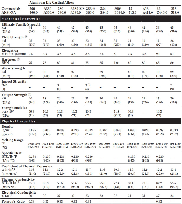
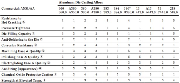
Material Selection
Product design can vary significantly depending on the choice of materials. Each alloy has certain limitations. To achieve the best integrity and strength of aluminum die castings, careful design and execution are required.
Depending on the composition of the alloy elements used in aluminum, its weight, fluidity, strength, conductivity, melting point and other properties may vary. However, not all alloy elements are suitable for casting materials.
Some popular aluminum alloys that can be used for die-casting include:
- A380
- A383 (ADC12)
- A413
There are many other types of aluminum alloys available. You must choose the appropriate one based on your specific needs and budget constraints.
Draft
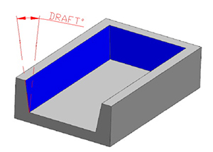
The draft angle is one of the important design parameters in aluminum die casting. It refers to the degree of taper or inclination between the core and the surface of the part and the parting line of the mold. We also call it the draft angle.
The designer must provide sufficient ejection angles when necessary. Because without adequate ejection angles, the castings will be difficult to remove after solidification, and there is still a possibility of damaging the parts or even the mold itself.
Design Considerations of Draft
When calculating the parting angle requirements, please take the following factors into account:
- Generally, a common chamfer angle is adopted for most geometric features.
- There are some exceptions for the interior walls and surfaces. In such cases, the ventilation volume is usually twice that of the exterior walls.
- The draft angle requirements may vary depending on the alloy used for casting. You may need to calculate the draft angle based on the type of aluminum alloy you have chosen.
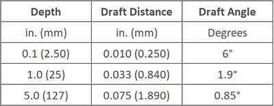
The following will illustrate the standard tolerances for the internal surface draft angles of aluminum castings of different depths.
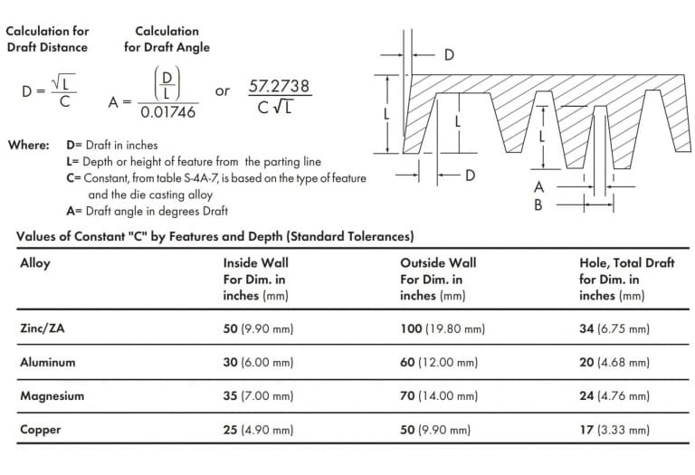
The standard tolerances for any alloy can be calculated using the following equation.
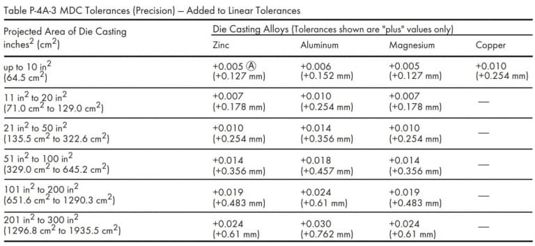
If you want to achieve a smaller draft angle, you can use precise tolerances. However, this requires more precise processing and incurs higher costs. Therefore, it is recommended to avoid using precise tolerances unless it is absolutely necessary.
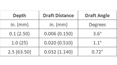
The accuracy tolerances for the internal surface draft of aluminum castings of different depths are as follows.
This is the formula for calculating the tolerance of part accuracy.
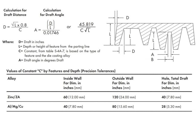
Please note that the draft diagram above has been exaggerated for better understanding of the concept. In fact, the draft diagram is very small and, if not observed carefully, it is usually impossible to notice at all.
Moving Die &Fixed Die
The coordinated design of the moving mold and the fixed mold is of vital importance. Even if one of them is inconsistent, it will hinder the aluminum die-casting process. The design of the moving mold is usually more challenging. The structure of the fixed mold is relatively simple, but the moving mold needs to handle more components. When the material is injected into the mold, due to the pressure of the excessive material, the core may slip out, resulting in oversized dimensions.
The tolerances of the moving mold components depend on the linear tolerance and the projection area tolerance. Among them, the linear tolerance refers to the length of the mold core slider, while the projection area refers to the head of the mold core slider facing the molten material.
The movement can be carried out along a linear direction perpendicular to the projection area. Therefore, it is best to keep the tolerance for moving the mold components at the minimum value of zero degrees.
Due to the structure of the die-casting equipment, only relatively large or positive tolerances can be allowed during the production process. Based on certain projected area variables, the standard tolerances and precision tolerances are as follows. NADCA guideline.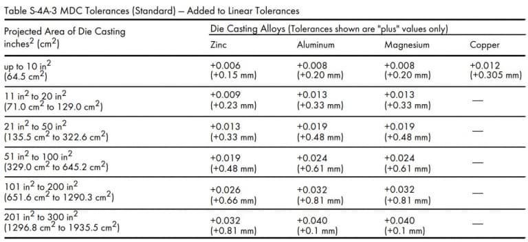
Parting Line
The parting line is the position where the two halves of the mold come together to form the complete structure of the product. Due to the die-casting process, the formation of the parting line is inevitable. Because the design always includes at least two components.
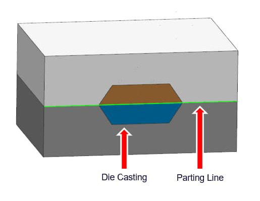
The parting line clearly indicates the distinction between the moving die and the fixed die of the mold. The parting line tolerance refers to the maximum amount of mold separation that is allowed to ensure the proper execution of the aluminum die-casting process.
When the material pressure tries to force the two halves of the mold to separate, the material will flow out from the separation point along the parting line. This is the flash defect in die casting. The casting requires additional finishing processes to remove the flash, risers, gates and overflow ports. The parting line tolerance is a function of the mold's projected area, which represents the separation surface where the molten material moves from one half-mold to the other.
The completely closed molds have no gaps between each other, so the tolerance of the projected area is always positive. The degree of mold separation depends on the mold shell pressure and the clamping force applied to keep the two halves of the mold closed.
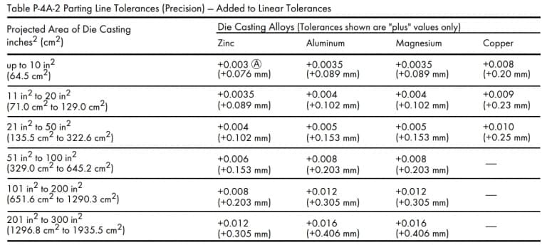
The parting line tolerance will vary depending on the alloy, size and depth of the part. The recommended standard tolerance values and precision tolerance values for the die-casting parting line are as follows.
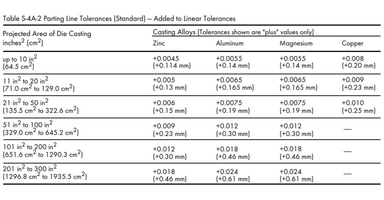
However, if the projected area of the die-cast part exceeds 300 square inches, please consult the die-casting factory (1935.5 cm²).
Machining Allowance
The machining allowance refers to the amount of raw material that can be removed from the finished aluminum die-cast part. The castings may have surface roughness and geometric shapes that deviate slightly from the actual design. Therefore, after die-casting, secondary processing is required to correct these errors.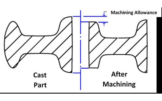
The key point is that the best mechanical properties and density of the castings are located at the surface or near the surface. Therefore, the machining allowance should be carefully determined to avoid penetrating the less dense parts.
However, during the design stage, a certain amount of machining allowance must be specified for the machining and casting variables. If the machining allowance is too small, it may fail to meet the surface quality requirements, and there is a risk of leaving defects in the parts.
On the other hand, excessive machining allowance for the parts will increase production time, labor costs and overall expenses. Consulting with the die-casting supplier in advance will help you determine the appropriate machining allowance.
Generally, the minimum machining allowance should be 0.010 inches (0.25 millimeters) to reduce tool wear and minimize the porosity of the castings. The maximum machining allowance is the sum of the minimum machining allowance and the deformation of the castings.
The following is an example of the comparison of machining allowances at two different reference point positions.
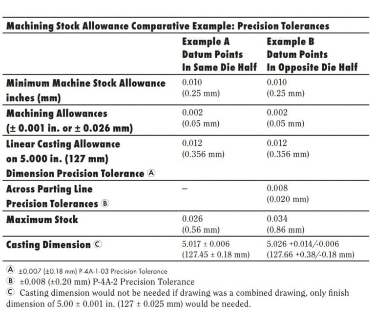 However, some additional consideration is needed for flat and large parts. You can consult with your caster to assure the machining allowance values in this case.
Wall Thickness
Always try to keep the wall thickness of the entire component uniform. Uniform thickness is beneficial for the better flow and solidification of the metal. Therefore, the quality and integrity of the casting will be better.
However, if you must provide variable wall thicknesses in your design, you should introduce a gradual transition in the form of rounded corners/radii instead of abruptly changing the thickness. Otherwise, sharp edges will remain in your design.
In product design, there should be no sharp edges. This is because it will affect the flow of the metal and make it difficult to remove the mold after casting. However, if the walls meet at the parting line, these edges can be retained.
Recommended Wall Thickness
Although there is no absolute standard for wall thickness or thinness, it is best to keep it within a certain limit. The typical wall thickness range for aluminum die castings is 0.0787 inches (2.0 millimeters) to 0.1378 inches (3.5 millimeters). This also depends on the size and structure of the part.
However, this may vary depending on the alloy of the casting, the configuration of the part, the size of the part, and the application. For instance, if the part size is small, it is possible to cast a wall section as thin as 0.020 inches (0.50 millimeters).
However, there may be exceptions to the maximum and minimum wall thickness for both small and large aluminum castings. If you encounter any issues, you can consult your casting factory.
Avoid Too Thick and Thin Wall
Increasing the wall thickness will enhance the rigidity of the part. However, an excessively thick wall will delay the cooling process, thereby hindering the solidification process. Therefore, unless appropriate measures are taken, it will result in poor quality of the casting.
Thick walls will also increase the weight of the product. Therefore, product designers who focus on reducing the weight of components tend to prefer using thin walls. However, if the wall thickness exceeds a certain limit, the stiffness will be too low, and it is prone to warping during further processing.
The warping problem can be solved through gradual processing. However, the thin walls of the castings lack rigidity and strength. Installing reinforcing ribs can significantly enhance the rigidity of the thin walls, making them more stable.
However, modern die-casting technology is already advanced enough to handle most of the key design parameters. But these technologies should only be considered if they can ensure better performance or economic benefits for the parts.
Lightweight Design
Metal retainers and grooves are two common design features of lightweight component design. They can significantly reduce the amount of material required for manufacturing the components, while not affecting their integrity and strength.
Metal space-saving refers to the hollow spaces typically found within reinforcing ribs, which are used to reduce material usage and thereby decrease the weight of the component. The sections between the reinforcing ribs are of little use and can therefore be safely removed from the design.
Design Suggestions for Metal Protectors
When designing the metal protectors for the parts, the following points should be kept in mind.
- Avoid sharp edges on the metal protectors. Use rounded corners/radii with as large a radius as possible. The minimum radius should be 0.06 inch (1.524mm).
- Maintain uniform wall thickness around the metal protector. Try to make the thickness close to the usual recommended value.
- Provide an as large an undercut angle as possible.
Pockets Can Significantly Reduce Weight
The bag-like structure is another weight reduction technique. The thin-walled part can be used to replace the thicker part with holes, thereby reducing the amount of material required for production. However, the bag-like structure sometimes causes irregular shrinkage.
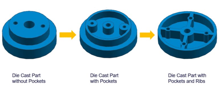
Therefore, you should carefully decide where to use the cavities. You can also use reinforcing ribs to enhance the structure of the cavities. This will increase the stiffness of the cavities and improve the metal flow. Reducing the amount of metal used can also increase the cooling speed, thereby shortening the production cycle.
Fillets & Radii
Although it is widely believed that rounded corners and radii are not the same thing, they are indeed different. While both refer to the rounded edges in the design of aluminum die-cast parts, the smooth inner angle is called a rounded corner, and the smooth outer edge is called a radius.
For any aluminum die-casting design, round corners and radii are extremely important features. They can significantly reduce the turbulence generated during the metal injection process, ensuring smoother metal flow. As a result, the parts can achieve better structural integrity.
Suggestion for Designing Fillet/Radii
- When two intersecting surfaces have sharp corners, using rounded corners or radii to connect them can prevent high stress concentration in that part of the mold or the component.
- Fillet/Radii: For any edges or corners along the parting line of the mold, no fillet/radii are required.
- Provide sufficient draft angle for the fillets that are perpendicular to the parting line.
You can design the fillet/radii in the parts according to the following guidelines.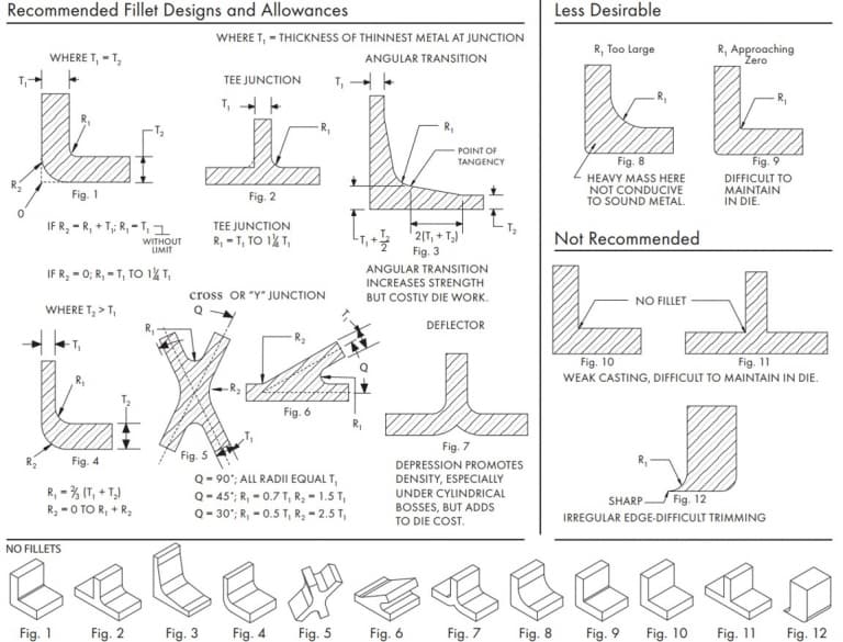
Shrinkage
Shrinkage is a very common and inevitable phenomenon. When any metal alloy is in the process of cooling and solidifying after being melted, there will be a certain degree of contraction. Therefore, designers must make necessary adjustments to the product design to leave space for shrinkage.
A thicker section is prone to shrinkage, which leads to the formation of pores inside. Local overheating can also cause shrinkage and subsequently result in pores. It is necessary to improve the mold design to locally cool these areas. However, this may increase the casting cycle.
Techniques For Reducing Casting Shrinkage
Designers should follow the following design considerations to reduce the shrinkage of aluminum castings.
- In the design, excessive or thick sections should be avoided. If possible, the design should be revised to use thinner sections and core materials that save metal.
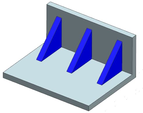
- Adding flat or vertical ribs to the wall can improve the feeding characteristics and reduce the tendency of shrinkage.
- Adding compression pins can reduce shrinkage in specific areas.
Boss
For the parts that need to be installed in other locations, the bosses are indispensable. They serve as support and installation points. However, if the design and positioning of the bosses are improper, it may lead to manufacturing difficulties and thus increase costs.
The bosses will also increase the material requirements and the weight of the aluminum castings. The protrusions can be redesigned in the following way to obtain lighter parts.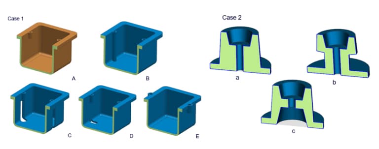
Design Considerations for Boss Design
The following are some design considerations that should be taken into account when designing the bosses in the parts.
- If a hole is required, try adding a hole at the center of the raised platform to achieve uniform wall thickness.
- Provide larger rounded corners for the protrusions to allow the molten metal to flow in appropriately.
- It is recommended to add ribs, as they can help ensure a good filling of the protrusion and also provide additional strength to the protrusion.
- Provide sufficient ventilation for the protrusion so that the castings can be ejected more easily.
This is a short video that explains the application and design process of the raised platform in die casting.
Ribs
The design of the reinforcing ribs is aimed at increasing the stiffness of the aluminum die-cast parts, thereby enhancing their strength. Therefore, the reinforcing ribs contribute to the robustness of the castings. They are usually used in combination with other weaker parts (such as thin-walled sections) to enhance their strength.
Its relatively thick solid cross-section typically provides higher strength because a thicker section usually has a higher porosity, thereby reducing its structural load-bearing capacity. However, excessive use of reinforcing ribs can lead to stress concentration at the edges of the reinforcing ribs.
The reinforcing ribs are usually designed with a hollow cross-section, also known as a metal-saving body. This approach can reduce the material usage of the reinforcing ribs, thereby reducing the weight of the parts.
The figure below shows the recommended rib sizes for some common scenarios and also indicates some situations where ribs should not be used.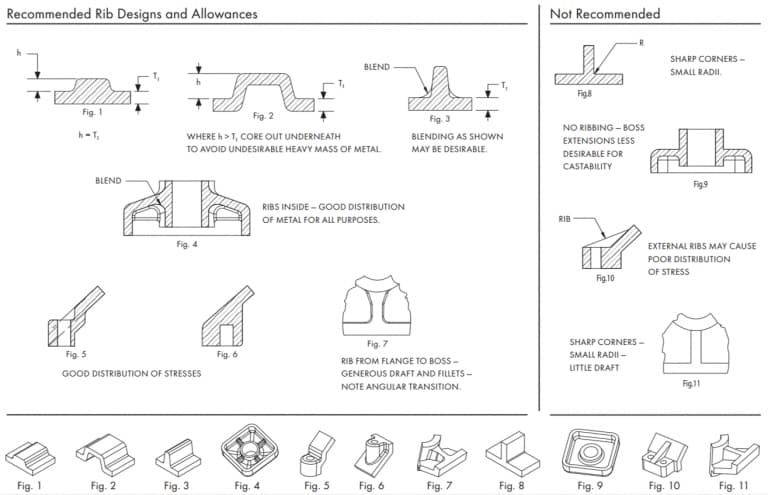
Hole to Edge Space Design
If the hole is too close to the edge of the aluminum casting, the cross-sectional strength will decrease. The minimum distance between the hole and the edge should be maintained to avoid excessive stress concentration in this area. Therefore, the appropriate distance between the hole and the edge should be determined based on the diameter of the hole. The minimum clear distance between two adjacent holes should also be maintained. For this purpose, the diameters of the two holes and their stress concentration areas should be considered.
The sufficient spacing is to avoid weak areas. If the distance between the hole and the edge is insufficient, secondary processing can also be considered.
Hole and Window
In terms of design difficulty, holes and windows are usually the easiest to handle. However, even the simplest features in aluminum die-cast parts require careful attention to details during the design process. During the design, it is necessary to ensure manufacturability.
 The most common applications of holes and windows are in the casings of various electronic devices, such as laptops and calculators. These devices require many holes to be placed. This layout causes problems for the flow of metal.
You can better understand this issue intuitively through this video.
Holes and windows can also make it difficult to remove the castings. This is because the solidification shrinkage of the parts can cause the castings to get stuck in the mold. When designing holes and windows, you can follow the following tips to solve these problems.
- Provide sufficient demolding capacity to solve the ejection problem. From the calculation of demolding capacity, you will notice that: holes and windows require a larger demolding capacity than any other structure. This is because flat and closed walls are set along the inner circumference.
- To prevent any problems during the metal flow process, you can use a bridge-like structure to ensure that the metal can flow continuously through the holes and windows. Providing lateral feed ports, burr and overflow ports can ensure smooth flow of the metal within the component. You can easily trim these additional structures later.
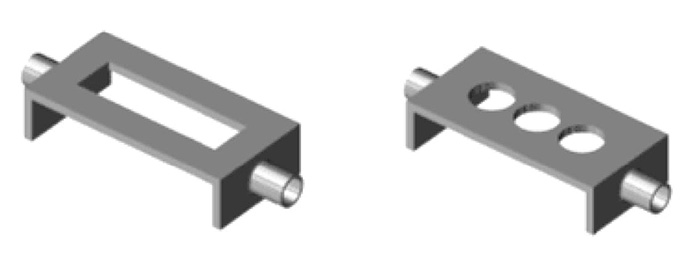
- If your design permits, you should remove the large window and replace it with a series of small holes. Because long windows can disrupt the metal flow and compromise the integrity of the casting.
Try To Avoid As Much As Possible
Designers should attempt to align these geometric features parallel to the mold ejection direction, or redesign the part to eliminate the need for the core/slide. The following example shows how to redesign the part to eliminate the requirement for side cores.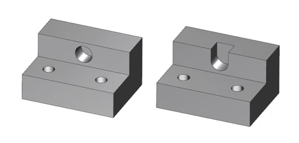
However, in some cases, you must introduce cores/slides to cast the features without the need for subsequent processing. You can design core slides or pull rods to eliminate the need for most (if not all) of the secondary processing operations.
Therefore, the difficulties caused by the increased initial mold cost and the prolonged casting cycle can be mitigated by reducing the number of secondary processing steps. As a result, the repeatability of the parts has been significantly improved.
Working Mechanism
The side core-pulling mechanism and slider movement are usually driven by inclined pins or hydraulic cylinders. The inclined pins are mechanical devices used for the core-pulling/slider movement. The opening and closing sequence of the main mold can activate the inclined pins.
Therefore, the inclined pins can be used without an additional power source. The production cost is also lower. However, the inclined pins may interfere with the disassembly of the castings, and they are only suitable for shorter slides.
The top slider also has difficulty using pin joints and can only use springs. Using a hydraulic method can solve these problems. You can define a cycle and use the top slider. It will not interfere with the recycling of the castings.
There are other motion methods that can be used for the core/ram. The designer must choose the appropriate motion method based on factors such as budget, production volume, part size, and the travel length of the core/ram in the casting.
You can discuss with your die-casting factory to obtain appropriate suggestions regarding the design of the side core-pulling/slide mechanism. We also welcome your inquiries and will do our best to assist you.
Thread Forming
When we talk about thread forming, we mainly focus on casting external threads. Although internal threads can theoretically be cast, due to the complexity and cost of the manufacturing process, internal threads are not ideal.
The external thread can be easily manufactured by using a conventional aluminum die-casting device and properly aligning the parting line, or by using a simple slider mechanism. The internal thread, however, requires an assembly to rotate the core in the mold.
This will increase the cost of tools and parts. To enhance production speed and economy, internal threads are usually processed as a secondary operation. This way, there is no need to remove chips from the hole.
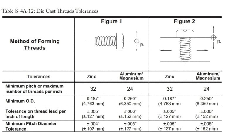
Ideal Tolerances of Threads
The threads can be easily formed by an aluminum die-casting machine. The cast threads are usually limited to external threads that do not require precise level of fit.
If you need a specific precision grade for your part, you can always consult your die-casting factory. Secondary processing To achieve better precision, adjustments may be necessary. Additionally, the major diameter should follow the specified thread profile definition agreed upon by both parties.
The maximum and minimum tolerances for some ideal thread forming operations are as follows:
Thread Design Considerations
However, when creating threads, please keep the following points in mind.
- Additional trimming operations may be necessary to remove any burrs formed between the threads.
- Try to apply direct tolerances as much as possible instead of specifying the thread fit grade.
- These values include the tolerance limits for the moving mold components, parting lines and linear dimensions.
- When more stringent thread tolerances are required, please consult the die-casting factory.
- Keeping the threads at the parting line smooth can significantly simplify the manufacturing process. Since full-diameter threads are not necessary. Keeping the threads smooth allows the mold to move slightly without affecting the part.
The following chart shows the recommended external thread configuration.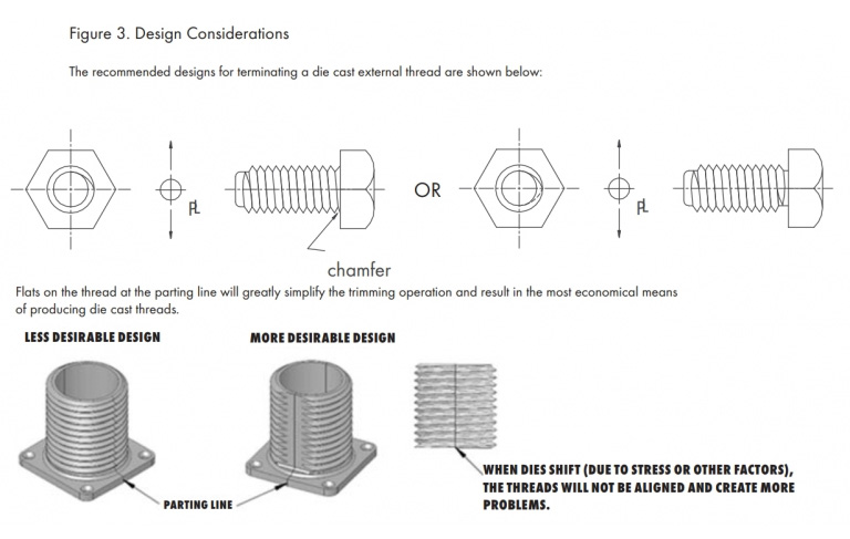
Insert
The insert is a solid piece of material that is embedded in the mold and integrates with the aluminum die-cast part. When the selected alloy fails to meet the requirements and the design calls for integrating components made of other materials, inserts are needed.
There are professional systems that can be used in aluminum die casting to incorporate inserts. The inserts are placed within the mold cavity, and the molten aluminum flows around the inserts, thereby completing the die casting process.
When you encounter the following situations, you may need to incorporate threaded inserts in your design:
- The bearing points are prone to wear and tear.
- Due to the excessive frequent disassembly and insertion of fasteners, the threads will be overly worn.
- When you need threaded components with higher tensile strength to handle concentrated loads.
Insertion die casting is more costly than conventional casting, and the complexity of the insertion setup can also affect the production cost.
Suggestions Regarding Insertion
- Clearly define all the specifications required by the die casting factory. Due to the large gap in the mold, the inserts usually require stricter tolerances. Please obtain the approval of the die casting factory to ensure that the tolerances of the inserts are sufficient.
- If the customer wishes to provide the blades, please negotiate with the casting factory to ensure that the tolerances are in line with the suggestions of the casting factory. Because blades with inappropriate tolerances may seriously damage the mold.
- Analyze the stress caused by the inserts. Ensure that these stresses do not have a long-term impact on the performance of the product.
- The insert can be shaped in any way as needed to ensure that it provides sufficient anchoring force for the expected load conditions.
- Avoid sharp corners and other features that may cause stress concentration in the parts.
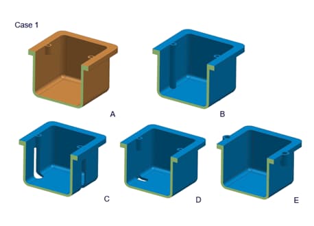
Undercut
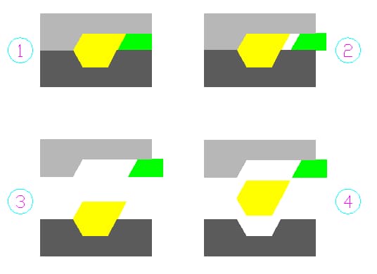
The undercut usually refers to the concave geometric features or surfaces on a part that cannot be reached by a straight knife. In the die casting process, the undercut refers to the feature that restricts the casting from being ejected by a single pulling mechanism.
Therefore, when designing the parts, it is necessary to take into account the difficulties that may arise during the machining and casting processes. Sometimes, you can eliminate the effect of undercut by skillfully choosing the direction of aluminum die casting. However, in most cases, this cannot be achieved without introducing side cores.
Adding side cores to the design will make the mold structure and casting process more complex. Compared with the traditional aluminum die casting, the mechanism of side cores is more complicated, thus resulting in higher costs and requiring more time for setup.
When designing the undercut, it is essential to keep the following important points in mind.
- Discuss with your manufacturer whether it is possible to use specialized cutting tools that can reach hard-to-reach areas, such as T-shaped or V-shaped tools.
- Try to minimize the number of external cores. Because they require side cores, which will increase the cost of the mold.
- Adjusting the parting line can solve some undercut problems.
- Re-design your part to eliminate the internal undercut.
- Avoid undercutting that is not oriented towards the mold pulling direction. If side cores are not placed, they cannot be ejected.
- The undercutting below the boss will hinder the ejection of the aluminum casting.
However, if possible, it is best to avoid any kind of undercutting in the design.
Gutter Design
A slot is a narrow hole, and its end may have a rounded edge or may not. It mainly appears on flat rectangular aluminum parts. Its length is usually limited. The slot is always continuous, meaning it will completely penetrate the part.
Depending on the length and shape of the groove, there can be different types of grooves, such as length-bounded on both sides, length-bounded on one side, or a semi-circular elongated groove.
The grooves can be composed of various shapes and sizes, such as T-shaped grooves, dovetail grooves, rectangles, flat bottoms, V-shaped grooves, arcs, etc. They are usually cut along the edge and serve as features for installing components made of other materials.
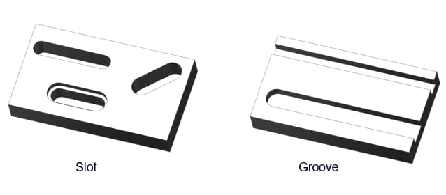
The slots and grooves in the design can serve as clamping elements for other components. They also provide openings through which other components (such as switches, levers, etc.) can pass.
When designing slots and grooves, the following tips might be helpful.
- Please remember that slots and grooves can hold or transfer the dimensions of other components.
- In the design, slots with too close spacing should be avoided. These slots will affect the integrity of the parts and cause problems during the finishing process.
- Do not leave any sharp edges in the rectangular/flat-bottomed groove. Try to round off all the inner and outer edges as much as possible. This will help minimize the electroplating cost and reduce minor problems.
- For the same reason, the angle of the V-shaped groove should also be circular.
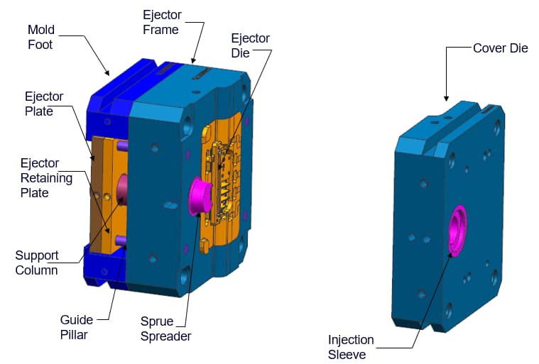
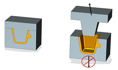
Injector Design
Due to the solidification shrinkage, the solidified aluminum castings are prone to getting stuck in the mold. Therefore, some ejection components are needed to apply additional force from the inside of the mold to ensure that the castings can be ejected.
The ejection mechanism of the die-casting equipment can be composed of multiple components. The die-casting mold mainly consists of two parts, namely the cover mold half and the ejection mold half. The ejection mold contains the ejection mechanism.
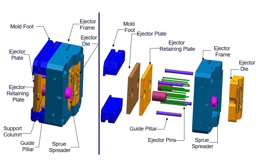
The parting line is the point where the two halves of the mold separate. After the casting is completed, the ejector mold separates from the parting line. However, due to the more complex equipment and multiple mold configurations, this makes the ejection system more complicated.
We will only discuss the traditional two-part molds, as these are more common and cost-effective. In this case, the ejection part of the mold includes pins, ejection plates, inserts, runners, and any engraved patterns present in the design.
The ejection mechanism mainly depends on two components of the mold: the ejection pin and the ejection plate.
Ejector Pin
The function of the push rod is to push the solidified casting out of the mold. Another function of the push rod is to clamp the casting to prevent it from bending due to the concentrated stress during the solidification process. However, the disadvantage of the push rod is that it will leave marks on the casting.
Therefore, designers should carefully select the position and size of the push rod based on the size, structure and other factors of the casting. When designing the push rod, the following guidelines should be followed.
- Place the ejector pin in the non-functional area of the casting, such as the bottom of a deep cavity, the overflow port, the protrusion, or the bottom of the rib.
- When removing the castings, the push rod will leave marks. Therefore, please do not position the outer surface of the castings towards the push rod.
- The recommended tolerance for the protruding or recessed pin marking is 0.015" (0.381 mm).
- Please follow the advice of the die-casting workers, as they can assist you in selecting the more appropriate size, position and quantity of the clamping pins.
The correct mold manufacturing method can significantly reduce the marks left by the push rod. However, these marks are still clearly visible. The original equipment manufacturer and the die-casting manufacturer should agree on the installation position of the push rod.
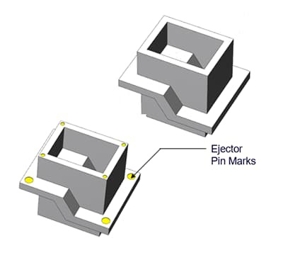
Also, please note that fringes will form around the top pin. Usually, unless the customer objects, fringes will not occur. The fringes of the top pin can be flattened to minimize their impact.
Ejector Plate
The ejector plate can serve as a supplementary component for the ejector pin, or it can be used independently. Usually, the casting factory uses the ejector plate as the installation surface for the ejector pin. Since the pressure is only applied to the ejector plate, the ejector pin will simultaneously push the ejector pin forward and retract the casting.
The ejector plate can also operate independently without the need for an ejector pin. However, we usually only see it in micro-molding. The force applied by the ejector plate to the part is used to eject it. The advantage of this is that the ejector plate does not leave any marks on the casting like the ejector pin does.
Sharp Edge
In the design of aluminum die castings, sharp edges should not be present. Sharp edges will create hotspots within the casting, and due to solidification shrinkage, these hotspots will cause stress concentration. This can lead to defects easily occurring at the corners. Moreover, it is also very difficult to apply coatings on sharp edges.
Therefore, designers tend to round off all the sharp corners, even if the radius is as small as possible. Apply rounded corners, radii or chamfers to all internal and external sharp corners. Here are some examples of sharp corner designs, and designers can redesign them in the following way.
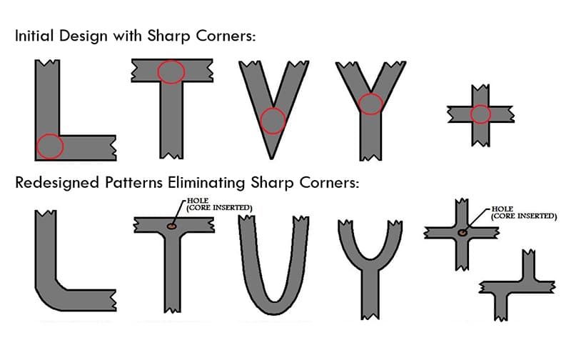
Another issue with the internal sharp edges is that they significantly increase the cost of the cutting tool. As is well known, the cost of mechanical processing is quite high, and the higher precision requirements will further increase the cost.
A perfectly sharp blade implies zero tolerance. Although an external blade can be achieved, the internal blade is almost impossible to reach such precision. Even with the most precise tools, the internal blade always has a minimum radius.
However, you can safely use sharp edges along the parting line to ensure that the two halves of the mold close completely. Besides, please try to minimize the use of sharp edges.
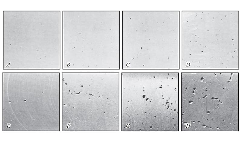
Pressure Sealing Property
Pressure sealing performance is an indicator for evaluating the integrity of aluminum die castings, indicating their ability to withstand a certain level of fluid pressure. In some cases, the purchaser may require the castings to have the specified pressure sealing performance.
The pressure sealing performance is largely determined by its density and porosity. Even a small amount of porosity can affect the pressure sealing performance of the component and may cause leakage during use. Various factors can influence the density and porosity of aluminum castings.
Air trapped inside the aluminum - this is a major concern for all manufacturers. When molten metal is injected under high pressure, the resistance caused by the trapped air can result in pores. The presence of air holes in the castings can also reduce their density, thereby compromising the structural integrity.
There are many factors contributing to the formation of pores, which makes it impossible for the castings to be completely pore-free. Effective DFM and good quality control throughout the production process will result in the appropriate density and the minimum porosity.
Factors Considered in Mold Design
Designers should take the following design parameters into account in order to achieve the best pressure sealing performance of aluminum die castings.
- Carefully follow the guidelines for round corners, reinforcing ribs and corner designs. Otherwise, the metal flow will not be smooth and turbulence may cause pores.
- Try to keep the wall thickness uniform to facilitate smooth metal flow. Avoid thick sections and any abrupt changes in thickness.
- For holes that require pressure sealing, the method of drilling should be used instead of mechanical processing to minimize the impact of porosity.
- All subsequent unprocessed holes and channels should be provided with sufficient draft angles. However, if the core holes are to be machined after casting, the minimum draft angle should be provided.
- Simulate the entire aluminum die-casting process to help you identify potential problems in advance. Run the mold flow analysis to determine which features of the mold can improve the quality of the castings.
- The vacuum-assisted die-casting equipment can significantly reduce the porosity of aluminum die-cast parts. As a result, there are fewer defects in the parts and better density performance.
Secondary Processing Operation
Secondary processing operations can also affect the pressure resistance of aluminum castings. The following guidelines should be followed during the processing.
- The most dense part of any casting is located on its surface or near it. The interior is usually less dense and has a higher porosity. Therefore, a minimum machining allowance should be specified to prevent the exposed porous parts in the interior of the casting.
- If the machining allowance required for the part exceeds the allowable limit, the internal porous parts may be exposed. Therefore, an additional impregnation treatment might be necessary to achieve the best sealing effect.
- Avoid processing the two sides of the castings that require pressure sealing.
- When processing a large number of blanks, it is advisable to avoid using a large draft angle. In particular, the minimum draft angle for the core hole should be taken into consideration.
In addition to the aforementioned considerations, the selection of the alloy plays a crucial role in ensuring the pressure resistance of the aluminum castings. Certain alloys perform better in terms of the pressure resistance of aluminum components.
Various testing equipment can be used to measure the pressure resistance of aluminum parts. Usually, pressure resistance tests are conducted within a pressure range of 5 to 40 psi. If higher pressure resistance is required, the designer should consult with the die-casting factory.
Part Strength
The strength requirements for aluminum parts will have a significant impact on the overall production cost and time. Therefore, you can clearly discuss the strength requirements of the parts with the die casting factory to select a feasible aluminum die casting design method.
The strength of aluminum castings depends on many factors. Here we provide some tips on how to ensure the strength of castings.
- Firstly, an appropriate type of aluminum alloy needs to be selected. The alloy used for production has a significant impact on the strength of the parts. However, mechanical strength is not the only crucial parameter. The chosen alloy must have sufficient machinability and meet other requirements as well.
- It is best to cast as many features on-site as possible. Any features that are processed later will cause processing stress on the aluminum components.
- Using the vacuum-assisted aluminum die casting process to reduce the porosity of the parts. This will increase the density of the parts, thereby enhancing the structural integrity and strength.
- Adding reinforcing ribs to the thin-walled part and the platform will enhance its stability.
- Sharp edges are the hotspots of stress concentration. Therefore, these areas are prone to failure. You should use rounded corners to increase the rigidity of the part.
Following these guidelines can help you enhance the strength of the die-cast parts. However, you also need to consider many other details. Please discuss with your die-casting supplier and seek suggestions on how to increase the strength of the parts.
Minor Features
The processing of minute features requires more precise tools. The time, cost and difficulty of processing minute features are all higher. Features with standard tolerances can be achieved at a relatively lower cost and with sufficient accuracy to meet the needs of any ordinary consumer.
However, if your part is used in a very complex application, you may need precise tolerances. Processing beyond a certain level is called micro-processing, and standard processing tools cannot achieve this.
Micro-processing deals with machining features with tolerances far less than one millimeter. Compared to any standard machining operation, its cost is prohibitively high. Unless it is absolutely necessary, designers must avoid achieving such high precision in their designs.
If the mold develops defects prematurely, it will result in considerable maintenance costs. Therefore, efforts should be made to minimize minor defects in order to reduce the cost of the mold.
Die-Casting Engraving
Most aluminum castings will have some kind of text or decoration. These texts or decorations can be letters, logos, trademarks, date codes or production numbers, which are useful for tracking the supply chain, promoting the brand, and achieving many other purposes.
Die-casting engraving or decoration can be achieved on the parts in three ways.
- As an elevated feature
- As a characteristic of depression
- The raised letters on the concave panel
Among these three methods, the most economical one is to keep the letters as raised parts. The raised parts on the aluminum casting require the concave parts of the mold.
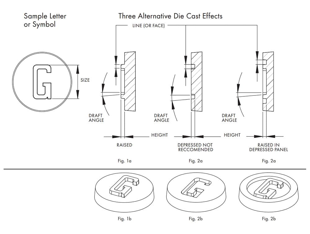
This feature is easy to be incorporated in the mold and causes minimal wear during operation. There are fewer raised (depressed) letters, and the construction cost of the mold as well as the maintenance cost throughout its entire service life are also lower.
On the contrary, the engraved characters on the aluminum castings require raised features, which will be raised into the mold steel. The construction is slightly more complex and the maintenance cost is also higher.
However, if the designer wishes to maintain a flat surface, then the text can be designed as a raised section within a recessed panel. This method is more practical as you can apply the recessed part without having to worry about damaging the mold.
Later, the coating can be used to fill in the additional recessed areas. Therefore, please avoid using recess features directly on the part.
Other Guidelines
- The surface (line thickness) of any letter or symbol should be at least 0.010 inch (0.254 mm) or larger.
- The height of the lines or symbols should be equal to or less than the thickness of the lines.
- If any text or decoration contains complex details or fine lettering, it may not be clear during the casting process. Therefore, please try to simplify them as much as possible.
- The draft angle should not be less than 10°.
Following these guidelines should be helpful for most situations. If you have any other requirements, you can always consult your casting factory for appropriate advice.
QR Code

Copyright © NINGBO CHIP MACHINERY CO., LTD. All Rights
Reserved
![]()